Difference between revisions of "Sample orientation"
KevinYager (talk | contribs) (→Reconstruction) |
KevinYager (talk | contribs) (→See Also) |
||
| (5 intermediate revisions by the same user not shown) | |||
| Line 1: | Line 1: | ||
For isotropic materials, the orientation of the sample with respect to the beam does not matter. However, for any sample that is anisotropic the '''sample orientation''' will strongly influence the scattering pattern. This effect is relevant for any intrinsically anisotropic material, including crystals and aligned bulk materials (liquid crystals, stretched polymers, etc.). Any material which has broken symmetry will also be anisotropic: e.g. a thin film is inherently different along the film normal than in the in-plane direction, and thus is not truly anisotropic. | For isotropic materials, the orientation of the sample with respect to the beam does not matter. However, for any sample that is anisotropic the '''sample orientation''' will strongly influence the scattering pattern. This effect is relevant for any intrinsically anisotropic material, including crystals and aligned bulk materials (liquid crystals, stretched polymers, etc.). Any material which has broken symmetry will also be anisotropic: e.g. a thin film is inherently different along the film normal than in the in-plane direction, and thus is not truly anisotropic. | ||
| − | Anisotropy in the sample is reflected in anisotropy in the [[reciprocal-space]]. Thus, the [[scattering]] pattern one observes on the detector will depend on the orientation of the sample with respect to the beam. | + | Anisotropy in the sample is reflected in anisotropy in the [[reciprocal-space]]. Thus, the [[scattering]] pattern one observes on the [[detector]] will depend on the orientation of the sample with respect to the beam. |
==Reciprocal-space== | ==Reciprocal-space== | ||
| Line 8: | Line 8: | ||
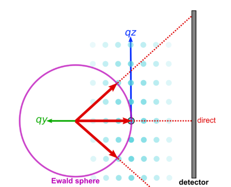
[[Image:R000.png|450px|thumb|center|Simplified 2D representation of a scattering experiment. The reciprocal-space of a crystal (blue), contains an array of peaks. The only peaks that are observed on the detector are those that intersect the Ewald sphere.]] | [[Image:R000.png|450px|thumb|center|Simplified 2D representation of a scattering experiment. The reciprocal-space of a crystal (blue), contains an array of peaks. The only peaks that are observed on the detector are those that intersect the Ewald sphere.]] | ||
| − | If we reorient the sample, we bring a different set of reciprocal-space peaks into the intersection condition. That is, we bring a different set of crystal planes in the sample into the 'Bragg condition' wherein they give rise to a diffraction peak. | + | If we reorient the sample, we bring a different set of reciprocal-space peaks into the intersection condition. That is, we bring a different set of crystal planes in the sample into the '[[Bragg's law|Bragg condition]]' wherein they give rise to a [[diffraction]] peak. |
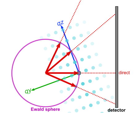
[[Image:R020.png|450px|thumb|center|A different sample orientation brings a different set of peaks onto the detector.]] | [[Image:R020.png|450px|thumb|center|A different sample orientation brings a different set of peaks onto the detector.]] | ||
==Reconstruction== | ==Reconstruction== | ||
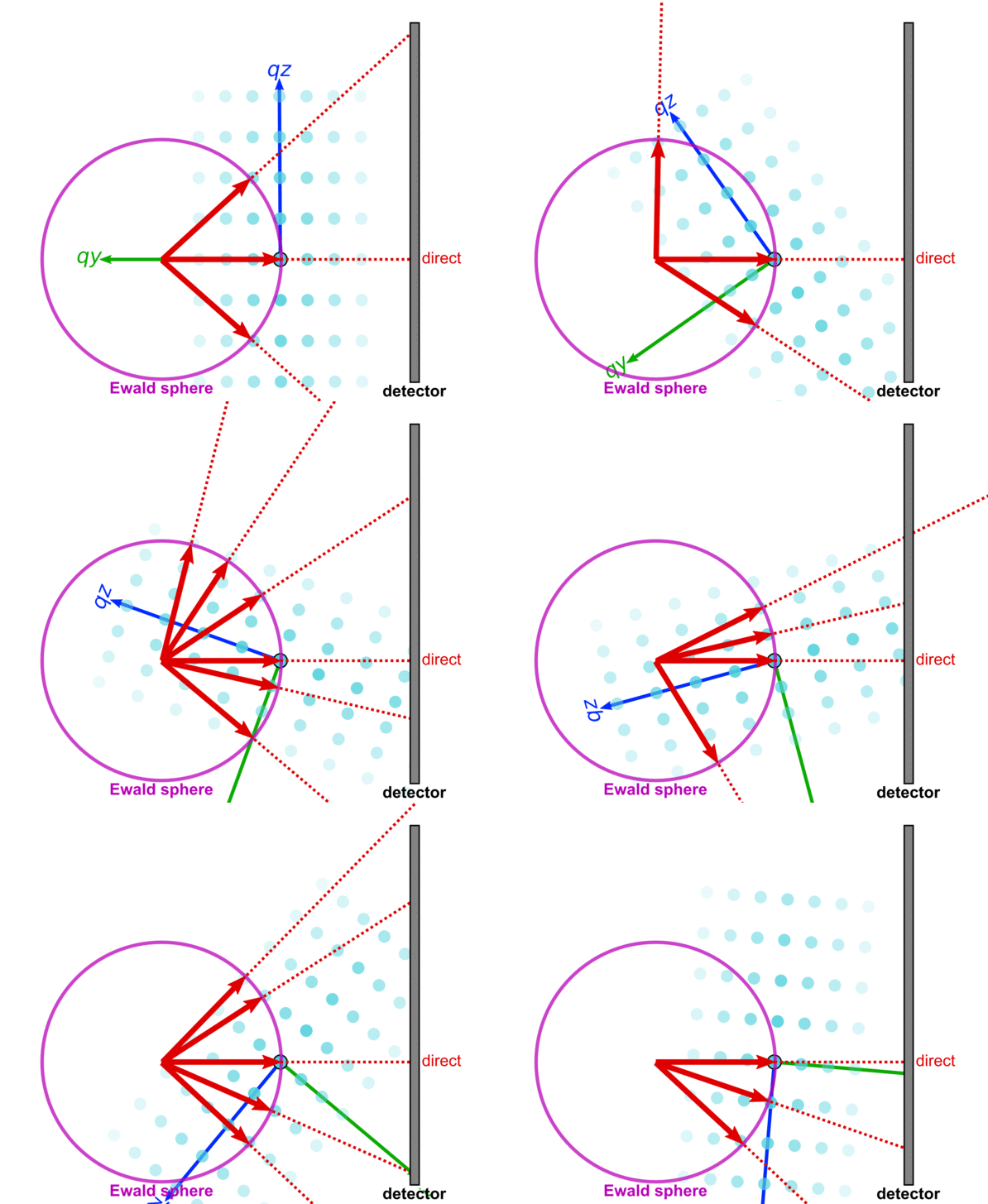
| − | In order to map out the entire reciprocal-space, one can completely rotate the sample, and collection a wide set of images. Adding these images together enables the full 3D reciprocal-space to be reconstructed. | + | In order to [[reciprocal-space mapping|map out the entire reciprocal-space]], one can completely rotate the sample, and collection a wide set of images. Adding these images together enables the full 3D reciprocal-space to be reconstructed. |
| Line 20: | Line 20: | ||
==See Also== | ==See Also== | ||
* [[Rocking scan]] | * [[Rocking scan]] | ||
| + | * [[Reciprocal-space mapping]] | ||
| + | * [[Example:P3HT orientation analysis]] | ||
| + | * L. Urzhumtseva and A. Urzhumtsev [http://scripts.iucr.org/cgi-bin/paper?gj5227 py_convrot: rotation conventions, to understand and to apply] ''J. Appl. Cryst.'' '''2019''' [https://doi.org/10.1107/S1600576719007313 doi: 10.1107/S1600576719007313] | ||
Latest revision as of 10:41, 8 July 2019
For isotropic materials, the orientation of the sample with respect to the beam does not matter. However, for any sample that is anisotropic the sample orientation will strongly influence the scattering pattern. This effect is relevant for any intrinsically anisotropic material, including crystals and aligned bulk materials (liquid crystals, stretched polymers, etc.). Any material which has broken symmetry will also be anisotropic: e.g. a thin film is inherently different along the film normal than in the in-plane direction, and thus is not truly anisotropic.
Anisotropy in the sample is reflected in anisotropy in the reciprocal-space. Thus, the scattering pattern one observes on the detector will depend on the orientation of the sample with respect to the beam.
Reciprocal-space
This is best understood in terms of reciprocal-space. Recall that the signal observed on the detector arises from the intersection of the Ewald sphere with the reciprocal lattice.
If we reorient the sample, we bring a different set of reciprocal-space peaks into the intersection condition. That is, we bring a different set of crystal planes in the sample into the 'Bragg condition' wherein they give rise to a diffraction peak.
Reconstruction
In order to map out the entire reciprocal-space, one can completely rotate the sample, and collection a wide set of images. Adding these images together enables the full 3D reciprocal-space to be reconstructed.
See Also
- Rocking scan
- Reciprocal-space mapping
- Example:P3HT orientation analysis
- L. Urzhumtseva and A. Urzhumtsev py_convrot: rotation conventions, to understand and to apply J. Appl. Cryst. 2019 doi: 10.1107/S1600576719007313


