Grating alignment
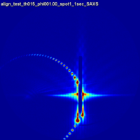
In order to align a lithographic (nanoscale) grating with the incident x-ray beam, one must rotate it carefully about the axis (i.e. the film normal direction) until the grating lines are exactly parallel to the incident beam. If the grating is not aligned, the scattering spots seen in GISAXS will not be symmetric.
Contents
Aligning
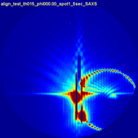
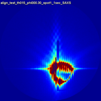
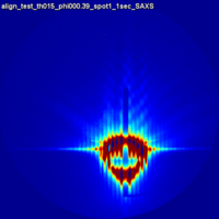
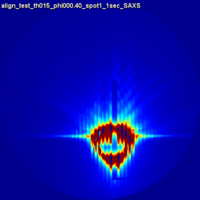
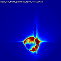
If the grating is not aligned with the incident beam, the scattering will be asymmetric, with a ring of peaks appearing on one side or the other.
- If "ring of spots" is on right you must rotate stage counterclockwise (as viewed from above)
- If "ring of spots" is on left you must rotate stage clockwise (as viewed from above)
Origin of Ring
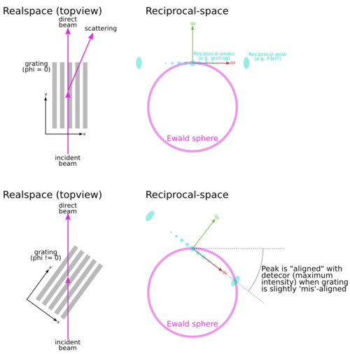
The "ring" of bright scattering spots that one observes arises from the intersection of the Ewald sphere with the reciprocal lattice. Because lithographic gratings are so well-ordered, the reciprocal-space peaks are extremely sharp. Thus, the scattering intensity is strongly concentrated into the plane. The curved Ewald sphere intersects this plane to give rise to a circle of intense scattering.
One can perform a 'phi rock': where one integrates the detector signal as the sample is rotated about the Failed to parse (MathML with SVG or PNG fallback (recommended for modern browsers and accessibility tools): Invalid response ("Math extension cannot connect to Restbase.") from server "https://wikimedia.org/api/rest_v1/":): {\displaystyle \phi} axis. This sweeps the Ewald sphere through reciprocal-space, effectively accumulating all the intensity that is along the Failed to parse (MathML with SVG or PNG fallback (recommended for modern browsers and accessibility tools): Invalid response ("Math extension cannot connect to Restbase.") from server "https://wikimedia.org/api/rest_v1/":): {\displaystyle (q_x,q_z)} plane in reciprocal-space. The end result is that the detector image includes the full array of diffraction peaks.
Grating with material
Lithographic gratings are often used to align other materials (small molecules, block-copolymers, semiconducting polymers, etc.). When assessing scattering data arising from such systems, one must be careful to correctly interpret the 'aligned' direction.
Let's say you align the grating at phi=0, and that there is a peak in reciprocal space at fairly large |q| due to some other material (let's say the P3HT 100). Normally we would say that if you see this peak on the detector when phi=0, then we can say the material (P3HT) is aligned with phi=0. However, this isn't quite right because of the curvature of the Ewald sphere. If the peak is truly aligned with the grating, then the peak on the detector will be maximized when we slightly offset phi, by just enough to counter-act the size of the Bragg angle.
Another way to think about it is to say that if you rotate your grating, and some peak is maximized at phi=gamma degrees, then you shouldn't really say "sample has maximum alignment at gamma", but actually "sample has maximum alignment at (gamma-correction)", where you calculation the correction based on the geometry, Bragg angle, etc.
Literature Examples
GISAXS from Gratings
- Direct structural characterisation of line gratings with grazing incidence small-angle x-ray scattering Jan Wernecke, Frank Scholze, Michael Krumrey Rev. Sci. Instrum. 2012, 83, 103906 doi: 10.1063/1.4758283
- Grazing-incidence small-angle X-ray scattering of soft and hard nanofabricated gratings D. R. Rueda, I. Martín-Fabiani, M. Soccio, N. Alayo, F. Pérez-Murano, E. Rebollar, M. C. García-Gutiérrez, M. Castillejo and T. A. Ezquerra J. Appl. Cryst. 2012, 45, 1038-1045 doi: 10.1107/S0021889812030415
- On the assessment by grazing-incidence small-angle X-ray scattering of replica quality in polymer gratings fabricated by nanoimprint lithography M. Soccio, N. Alayo, I. Martín-Fabiani, D. R. Rueda, M. C. García-Gutiérrez, E. Rebollar, D. E. Martínez-Tong, F. Pérez-Murano and T. A. Ezquerra J. Appl. Cryst. 2014, 47, 613-618 doi: 10.1107/S160057671400168X
GISAXS/GIWAXS of materials aligned using gratings
- Nanoimprint-Induced Molecular Orientation in Semiconducting Polymer Nanostructures Htay Hlaing, Xinhui Lu, Tommy Hofmann, Kevin G. Yager, Charles T. Black, and Benjamin M. Ocko ACS Nano 2011, 5 (9), 7532-7538 doi: 10.1021/nn202515z
- One-Volt Operation of High-Current Vertical Channel Polymer Semiconductor Field-Effect Transistors Johnston, D.E.; Yager, K.G.; Nam, C.-Y.; Ocko, B.M.; Black, C.T. Nano Letters 2012, 8, 4181–4186 doi: 10.1021/nl301759j
- Nanostructured Surfaces Frustrate Polymer Semiconductor Molecular Orientation Johnston, D.E.; Yager, K.G.; Hlaing, H.; Lu, X.; Ocko, B.M.; Black, C.T. ACS Nano 2014 doi: 10.1021/nn4060539

